How to read construction documents [A step-by-step guide]

By
Marketing Team
@Onetrace
Construction documents are the detailed drawings, specifications, and supporting information used to price, approve, and build a project.
As such, they are the main reference point for everyone involved in executing a construction project, from design teams to suppliers and subcontractors.
This makes creating accurate construction documents essential, especially when you consider that avoidable errors across the construction industry cost roughly £5 billion per year.
However, even the most accurate files are of limited use if you don’t know how to interpret them, which is why this guide explains how to read construction documents step by step.
Key takeaways
Construction documents are the foundation of every build
They bring together drawings, specifications, and schedules into one coordinated set of information that defines what needs to be built, how it should be built, and what standards it must meet.You don’t read construction documents in order
Understanding comes from moving between plans, sections, details, schedules, and specifications, using references to build a complete picture.General Arrangement plans are your starting point
GA plans give you the layout, dimensions, and structure of the building, helping you orient yourself before diving into more detailed information.Supporting documentation fills in the critical details
Drawings show what and where, while supporting documentation explains materials, methods, and performance requirements needed to build correctly.Using the latest information is essential to avoiding costly mistakes
Revisions happen often, and missing an update can lead to errors on site, clashes between trades, and rework.Digital tools make construction documents usable on site
Platforms like Onetrace help you manage drawings, mark them up, access them offline, and keep specifications and reports connected to the work, so teams stay aligned and avoid errors.
What are construction documents?
Construction documents are a coordinated set of technical information used to guide and deliver a building project.
They bring together input from architects, engineers, and specialists into a single source of truth that sets out what needs to be built, how it should be built, and what standards it must meet.
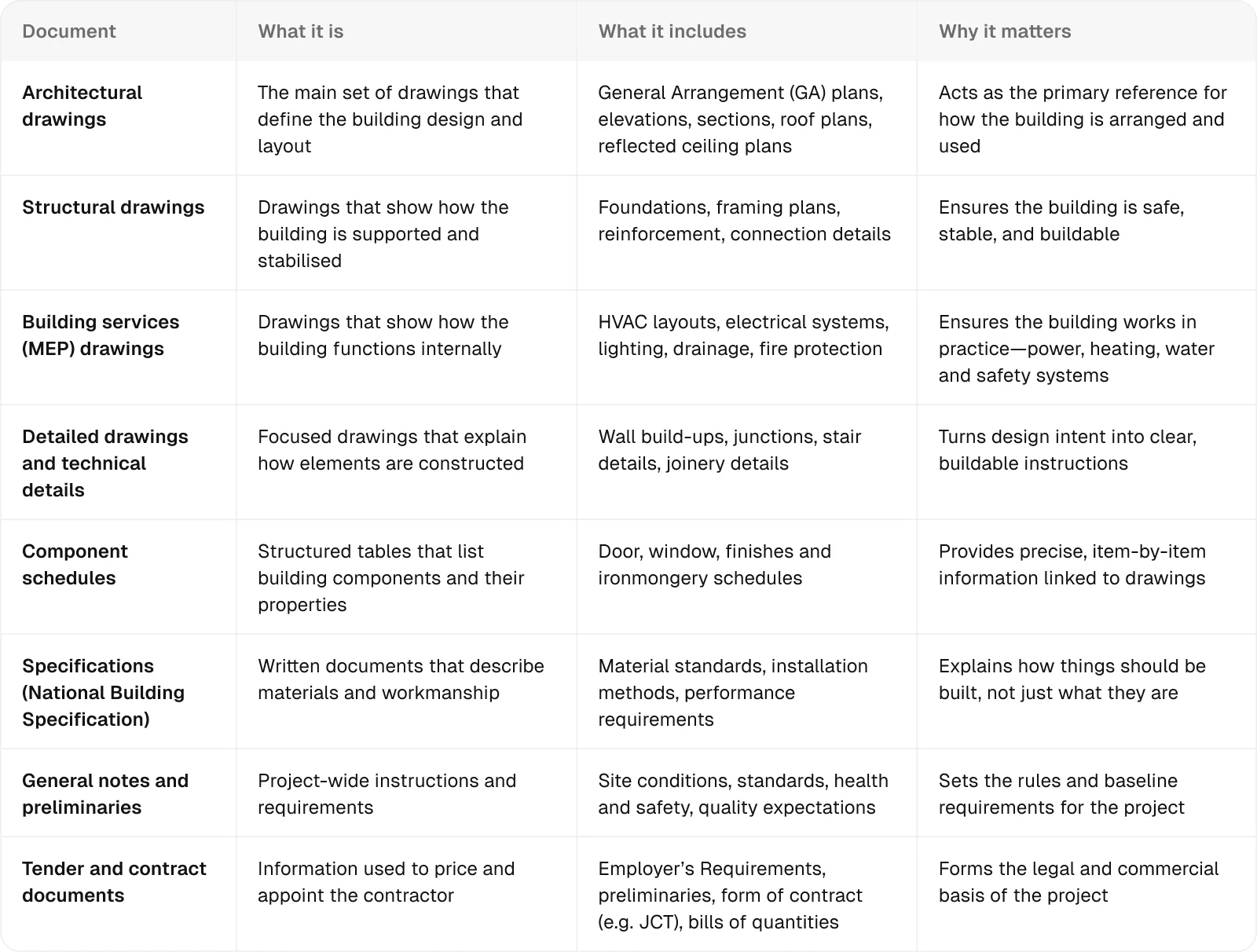
The table below outlines the main types of construction documents used on UK projects:
While construction documents are created during design, their real value comes during delivery, when they’re used by a wide group of people, each with a different focus.
However, for a project to run smoothly, everyone needs to be working from the same up-to-date information. This is where using a digital repository within construction site management software like Onetrace becomes important.
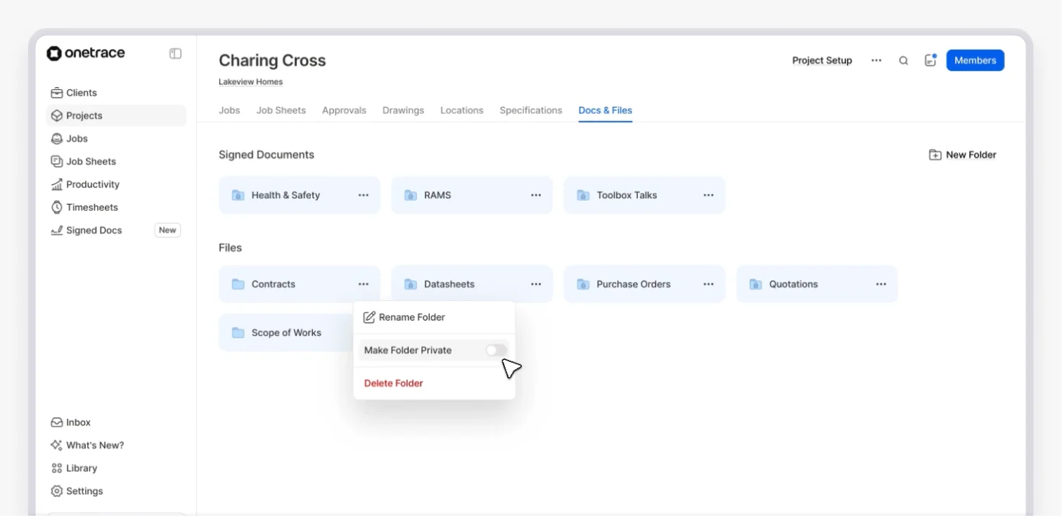
Onetrace helps bring structure to how documents are stored, shared, and used on site through:
Centralised storage: Keep drawings, specifications, solutions, RAMS, certificates, and other project documents in one secure place, so teams always know where to find the latest version.
Clear organisation across projects: Maintain a consistent structure so documents are easy to locate.
Document integration with site activity: Connect documents, such as risk assessments, specifications and test results directly to tasks and workflows, so they’re used in context.
Controlled access and visibility: Make sure the right people can access the information they need, while sensitive documents remain restricted.
How to read construction documents in 10 steps
When reading construction documentation, you move between drawings, notes, and specifications, building up an understanding by linking information together.
This step-by-step guide breaks down what that looks like in practice.
Step 1: Review the basic project context
Before looking at construction documents in detail, you need to understand what information is available and how it’s organised.
You can achieve this by looking at:
Drawing register: The drawing register lists all drawings included in the set and allows you to check whether you’re working from the latest revisions.
Sheet numbering system: The sheet numbering system shows how drawings are organised by discipline and type, helping you navigate the set quickly and locate the right information.
Title block: The title block is usually located in the bottom-right corner. It includes key details such as the drawing number, scale, status, and revision, all of which are needed to correctly identify and interpret the drawing.
UK projects often follow BS EN ISO 19650, which sets out how information is named and structured.
Drawing names use a coded format to identify the project, discipline, location, and type, with revision and status used to track updates, making it easier to find and manage information across the project.
Pro tip:
Different drawings use different scales depending on the level of detail, so checking this early helps you read sizes and distances correctly.
If a drawing is marked ‘do not scale’ or ‘not to scale’, you should rely only on stated dimensions rather than measuring directly from the drawing.
Step 2: Get familiar with symbols, abbreviations, and legends
Not all information in construction documents is written out in full.
Some details are shown using visual indicators, while other parts are shortened to keep drawings clear and efficient.
That’s why you need to get familiar with the following:
Symbols: Symbols are used to represent building elements or references, such as sections, elevations, doors, or levels.
Abbreviations: Abbreviations are used to keep notes concise. Common examples include ‘FFL’ (finished floor level), ‘CLG’ (ceiling) and ‘VIF’ (verify in field).
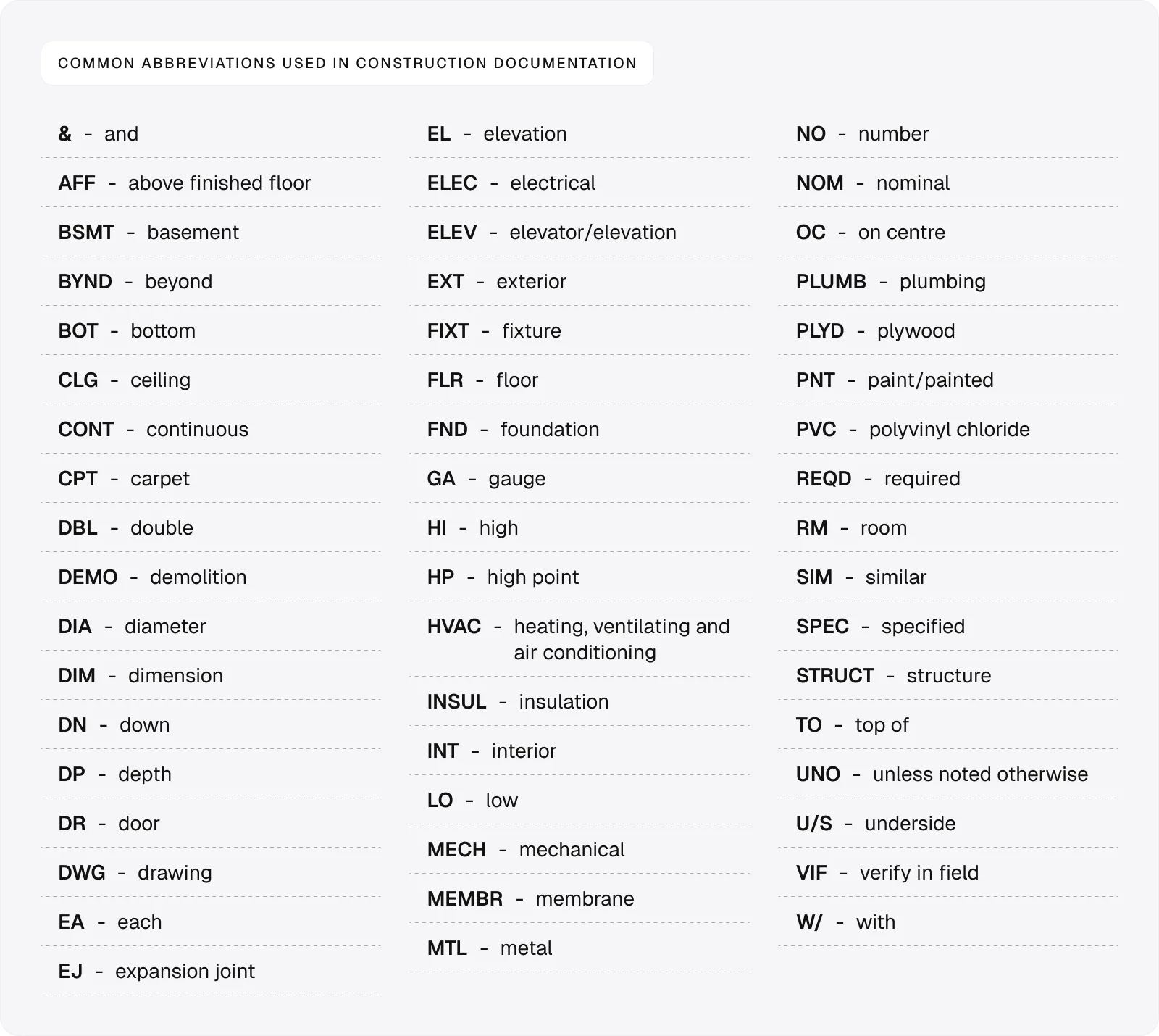
For the most part, you’ll need to understand abbreviations to read the annotations quickly.
Annotations are short notes placed directly on the drawing to describe materials, dimensions, or instructions. They give quick, essential context and often link to more detailed information in the supporting documentation.
As for symbols, you don’t need to memorise them, as you can typically find their meaning in the legend.
Besides symbols, the legend explains line types and hatch patterns used on the drawing.
Step 3: Focus on General Arrangement plans
General Arrangement plans are the main reference drawings that show the overall layout of the building.
They typically contain the following information:
Room layouts: These show how spaces are arranged and how they connect across the building.
Dimensions: These define the size and position of walls, openings, and key elements.
Grid lines: These provide a reference system used across all disciplines to align drawings.
Orientation: This shows how the building is positioned on the site and helps you stay consistent when reading other drawings.
Dimensions are one of the most controlled parts of a drawing set.
They follow consistent standards, are set out from fixed reference points, and are checked and rechecked before issue.
This level of control is what allows different teams to work from the same information without conflict.
Step 4: Build a vertical view with sections and elevations
Sections and elevations give you views of the building that can’t be understood from plan drawings alone.
Sections cut through the building to reveal internal structure, including floor-to-floor heights, while elevations show the building from the outside, including its height, form, and external materials.
Together, these drawings help you understand how the building works vertically and visually, turning a 2D plan into a 3D mental model.
Step 5: Find and read detailed drawings
Plans and drawings are often shown at a scale that can’t capture all the required detail.
That’s why they often include detail references, such as circled numbers or tags (e.g. ‘05/A-301’), which point you to more detailed drawings.
Use these to find elements like:
Wall build-ups: These show the full layer make-up of walls, including materials and thicknesses.
Junctions: These show how elements connect, such as wall-to-floor or roof edges.
Construction layers: These show how components are assembled in the correct order.
Step 6: Find information in schedules
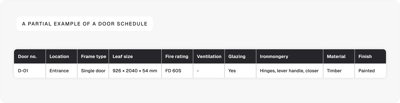
Drawings also contain tags linked to schedules, which are structured tables that list detailed information about building elements.
For example, a door marked ‘D-01’ on a plan can be looked up in the schedule to find its full specification, including:
Size (width, height, and thickness)
Material and finish
Fire rating
Ironmongery (hinges, handles, locks, closers)
Acoustic rating (if required)
Manufacturer or product reference
Other common schedules are:
Window schedules, which show dimensions, types, and specifications of windows
Finishes schedules, which list materials and finishes for each space
Step 7: Review structural and building services drawings
To fully understand the project, you need to look beyond the architectural drawings.
The two main reference points here are:
Structural drawings: These show foundations, beams, columns, and other load-bearing elements that support the building.
Building services drawings: These cover systems such as HVAC, electrical layouts, and drainage, showing how the building functions in use.
Step 8: Use specifications to understand requirements
Specifications set out the detailed requirements that sit behind the drawings.
While drawings indicate what is to be built and where, specifications define how it is to be built.
In the UK, specifications are often produced using the National Building Specification (NBS), a standardised system for organising technical requirements.
As such, they will include:
Material requirements: These define what materials must be used, including standards, grades, and approved products.
Installation methods: These explain how elements should be built or installed, including workmanship and sequencing.
Performance standards: These set out how elements must perform, such as fire resistance, acoustic performance, or durability.
Step 9: Connect information across documents
After reviewing each part of the construction documentation individually, use the built-in references to move between related drawings and documents and confirm they match.
Follow tags, callouts, and grid references to check that the same element is described consistently in plans, sections, details, schedules, and specifications.
This is how you catch mismatches early and make sure the information you’re relying on is complete and reliable.
Step 10: Confirm you’re using the latest version
Overlooking revisions is one of the most common and costly mistakes when reading construction documents.
Drawings are updated regularly, and working from an outdated version can lead to incorrect materials, wrong dimensions, and clashes on site.
Even small changes can have knock-on effects across multiple trades, so using the latest information is critical.
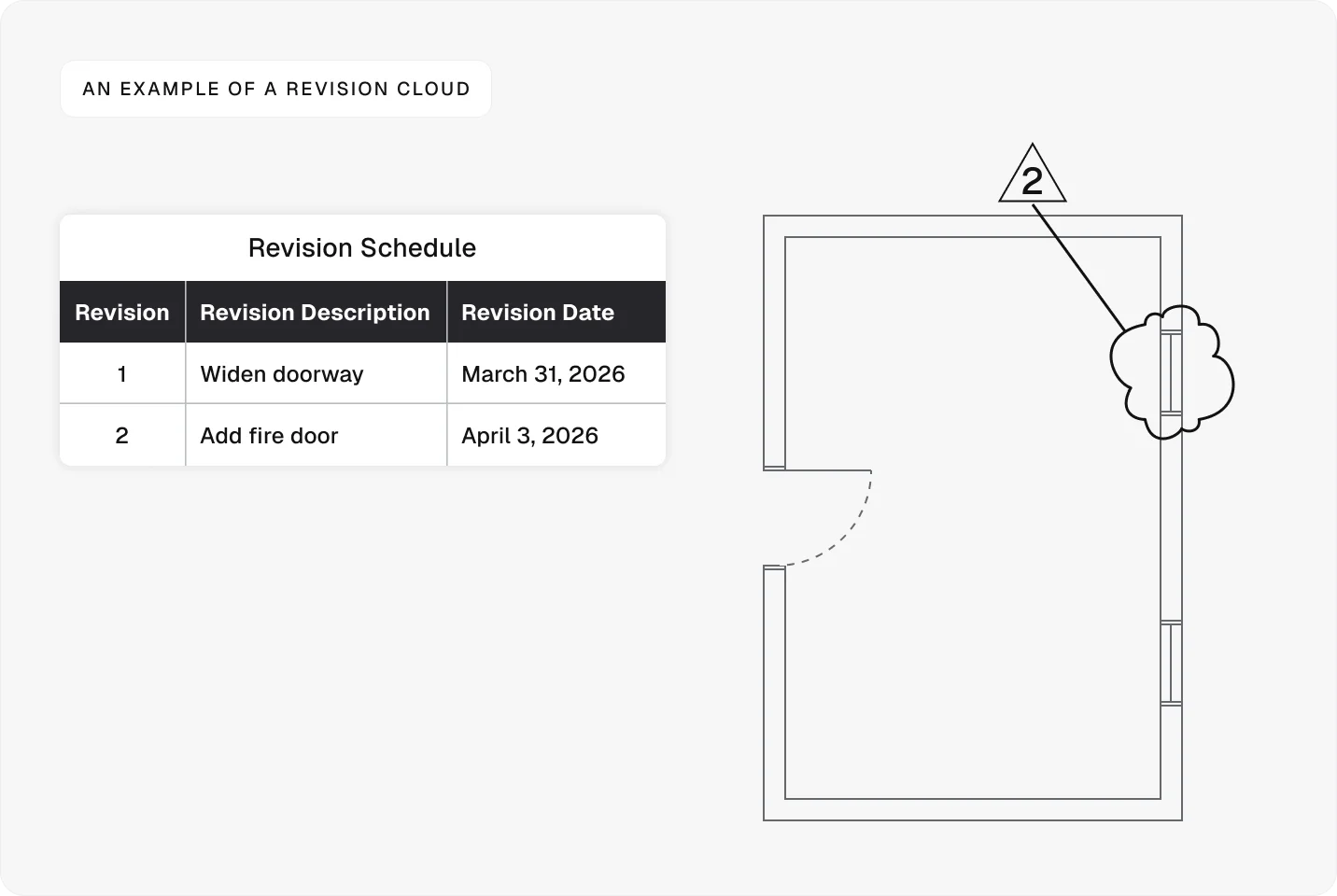
To ensure you’re using the most up-to-date information, check the revision block, which is usually located near the title block. Here, you’ll find the revision number, a description of changes, the date, and the name of the person who approved them.
As for the drawings themselves, they will display revision clouds—cloud-shaped outlines around parts of the drawing that have been changed since the previous version. These clouds are often paired with a number or symbol that links back to the revision block, where the change is described in more detail.
Using construction documents on site
Once you understand how to read construction documents, it becomes a skill you use throughout the entire build.
Every stage of a project relies on reading, checking, and applying information correctly, whether you’re coordinating work, resolving issues, or verifying what’s been built on site.
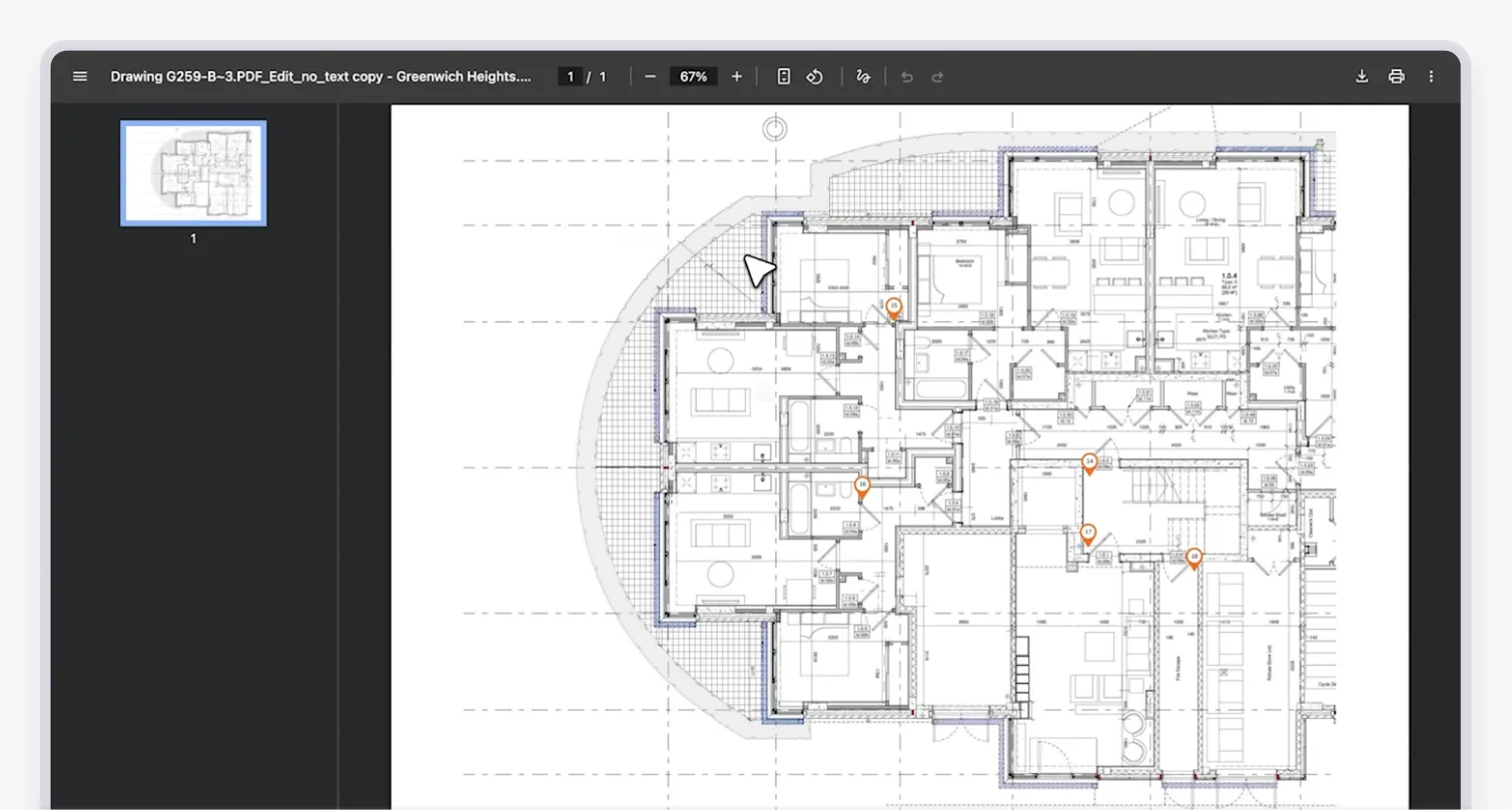
In practice, drawings don’t stay static.
They’re marked up as work progresses to highlight issues, record changes, and communicate with the wider team.
Thanks to tools like Onetrace, you can mark up drawings digitally, allowing the entire team to work from the same up-to-date information.
Besides being able to highlight areas, add notes, and record work directly on plans, you can also:
Create drawing-based projects: Run projects directly from drawings, organised by blocks and levels, so teams can track work visually on site.
Access drawings offline: Download drawings to mobile devices and continue working without an internet connection.
Generate drawing reports: Create reports from marked-up drawings to provide clear records of work completed and decisions made.
Onetrace also offers a dedicated Specifications tab, where you can store materials, files, and technical data alongside drawings for easy reference.
Thanks to these features, Onetrace keeps vital construction documents accessible and connected to the work on site, allowing you to operate more efficiently and with greater confidence.
To see how Onetrace helps you manage construction documents, track work on site, and keep teams aligned in practice, book a personalised walkthrough of the platform.
FAQ
Are construction plans hard to read?
Construction plans can be hard to read at first, but once you understand symbols, layouts, and the organisation of information, they become much easier to follow.
How to read a construction document?
To read a construction document accurately, start with the project overview, then read the plans, follow the references to sections and details, and check the schedules and specifications to build a complete understanding.
Can AI read building plans?
AI can help process and analyse drawings, but it still relies on human input to interpret context, coordinate information, and make decisions on site.
Marketing Team
@Onetrace
The Onetrace marketing team is passionate about sharing insights, ideas, and innovations that help construction businesses stay connected, compliant, and efficient. Combining industry expertise with a love for clear communication, we aim to deliver content that empowers professionals to work smarter and safer.